防火牆和核心交換機接口問題
- 0關注
- 0收藏,686瀏覽
問題描述:
核心是二層鏈路聚合組1000 VLAN1000 地址10.3.2.2 防火牆應該配置什麼接口和地址10.3.2.1對接核心的聚合組?
防火牆是創建reth 口 配地址 還是三層聚合口配地址 還是防火牆也創建vlan1000 和二層聚合 防火牆接口改成二層 然後對接核心交換機呢?
目前現網哪種使用比較多啊???reth和三層聚合的實驗案例有嗎? 謝謝指導
最佳答案

配三層口,三層口加入冗餘口
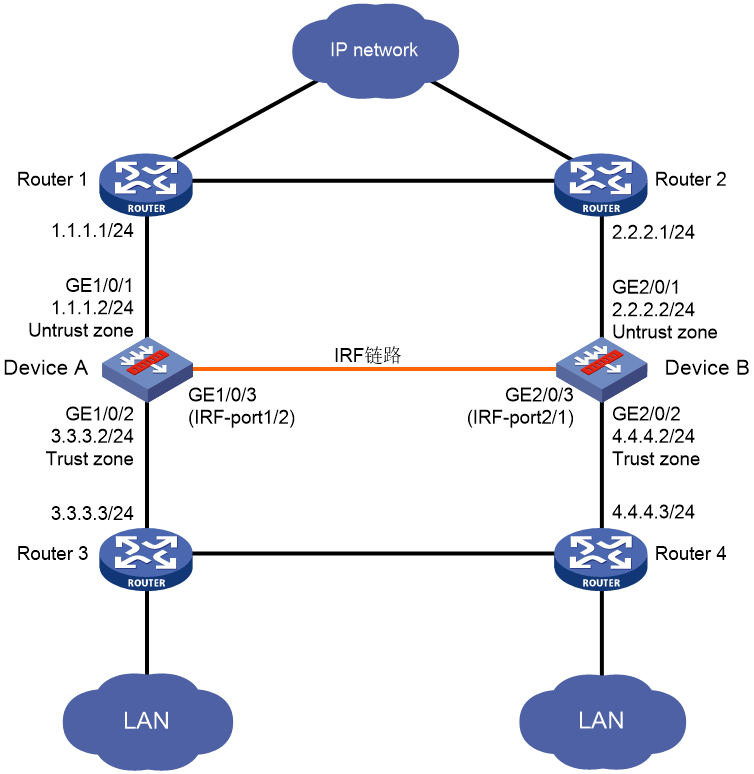
2.13.1 工作在三層,上下行分別連接兩台路由器,兩台路由器接口不在同一網段
1. 組網需求
· 如圖2-6所示,Device A和Device B組成IRF,Router 1和IRF相連的接口與Router 2和IRF相連的接口不在同一網段,Router 3和IRF相連的接口與Router 4和IRF相連的接口不在同一網段。
· 正常情況下,流量走Router 1——Device A——Router 3;當這條通道上的任一鏈路或者設備故障時,流量切換到Router 2——Device B——Router 4。正常通道故障恢複時,流量再切回。
2. 組網圖
3. 配置步驟
(1) 配置IRF
¡ 配置Device A
# 配置IRF端口1/2,並將它與物理端口GigabitEthernet1/0/3綁定,並保存配置。
<DeviceA> system-view
[DeviceA] interface gigabitethernet 1/0/3
[DeviceA-GigabitEthernet1/0/3] shutdown
[DeviceA-GigabitEthernet1/0/3] quit
[DeviceA] irf-port 1/2
[DeviceA-irf-port1/2] port group interface gigabitethernet 1/0/3
You must perform the following tasks for a successful IRF setup:
Save the configuration after completing IRF configuration.
Execute the "irf-port-configuration active" command to activate the IRF ports.
[DeviceA-irf-port1/2] quit
[DeviceA] interface gigabitethernet 1/0/3
[DeviceA-GigabitEthernet1/0/3] undo shutdown
[DeviceA-GigabitEthernet1/0/3] quit
[DeviceA] save
The current configuration will be written to the device. Are you sure? [Y/N]:y
Please input the file name(*.cfg)[flash:/startup.cfg]
(To leave the existing filename unchanged, press the enter key):irf-port-configu
ration active
The configuration file is invalid or not exist.
# 為確保Device A與Device B在主設備選舉過程中,Device A為主,修改Device A成員優先級為2(成員優先級大的優先,缺省情況下,設備的成員優先級均為1)。並激活IRF端口下的配置。
[DeviceA] irf member 1 priority 2
[DeviceA] irf-port-configuration active
¡ 配置Device B
# 將Device B的成員編號配置為2,並重啟設備使新編號生效。
<DeviceB> system-view
[DeviceB] irf member 1 renumber 2
Renumbering the member ID may result in configuration change or loss. Continue? [Y/N]:y
[DeviceB] quit
<DeviceB> reboot
Start to check configuration with next startup configuration file, please wait..
.......DONE!
This command will reboot the device. Continue? [Y/N]:y
# 參照圖2-6進行物理連線。
# 重新登錄到Device B,配置IRF端口2/1,並將它與物理端口GigabitEthernet2/0/3綁定,並保存配置。並激活IRF端口下的配置。
<DeviceB> system-view
[DeviceB] interface gigabitethernet 2/0/3
[DeviceB-GigabitEthernet2/0/3] shutdown
[DeviceB-GigabitEthernet2/0/3] quit
[DeviceB] irf-port 2/1
[DeviceB-irf-port2/1] port group interface gigabitethernet 2/0/3
You must perform the following tasks for a successful IRF setup:
Save the configuration after completing IRF configuration.
Execute the "irf-port-configuration active" command to activate the IRF ports.
[DeviceB-irf-port2/1] quit
[DeviceB] interface gigabitethernet 2/0/3
[DeviceB-GigabitEthernet2/0/3] undo shutdown
[DeviceB-GigabitEthernet2/0/3] quit
[DeviceB] save
[DeviceB] irf-port-configuration active
Device A和Device B間將會進行主設備競選,競選失敗的一方將重啟,重啟完成後,IRF形成。
(2) 配置Track,監測上、下行接口的狀態。
<DeviceA> system-view
[DeviceA] track 1 interface gigabitethernet 1/0/1 physical
[DeviceA-track-1] quit
[DeviceA] track 2 interface gigabitethernet 1/0/2 physical
[DeviceA-track-2] quit
[DeviceA] track 3 interface gigabitethernet 2/0/1 physical
[DeviceA-track-3] quit
[DeviceA] track 4 interface gigabitethernet 2/0/2 physical
[DeviceA-track-4] quit
(3) 配置冗餘組
# 創建Node 1,Node 1和Device A綁定,為主節點,成員接口為GigabitEthernet1/0/1和GigabitEthernet1/0/2。關聯的Track項為1和2。
[DeviceA] redundancy group aaa
[DeviceA-redundancy-group-aaa] node 1
[DeviceA-redundancy-group-aaa-node1] bind slot 1
[DeviceA-redundancy-group-aaa-node1] priority 100
[DeviceA-redundancy-group-aaa-node1] node-member interface gigabitethernet 1/0/1
[DeviceA-redundancy-group-aaa-node1] node-member interface gigabitethernet 1/0/2
[DeviceA-redundancy-group-aaa-node1] track 1 interface gigabitethernet 1/0/1
[DeviceA-redundancy-group-aaa-node1] track 2 interface gigabitethernet 1/0/2
[DeviceA-redundancy-group-aaa-node1] quit
# 創建Node 2,Node 2和Device B綁定,為備節點,成員接口為GigabitEthernet2/0/1和GigabitEthernet2/0/2。關聯的Track項為3和4。
[DeviceA-redundancy-group-aaa] node 2
[DeviceA-redundancy-group-aaa-node2] bind slot 2
[DeviceA-redundancy-group-aaa-node2] priority 50
[DeviceA-redundancy-group-aaa-node2] node-member interface gigabitethernet 2/0/1
[DeviceA-redundancy-group-aaa-node2] node-member interface gigabitethernet 2/0/2
[DeviceA-redundancy-group-aaa-node2] track 3 interface gigabitethernet 2/0/1
[DeviceA-redundancy-group-aaa-node2] track 4 interface gigabitethernet 2/0/2
[DeviceA-redundancy-group-aaa-node2] quit
[DeviceA-redundancy-group-aaa] quit
(4) 配置接口IP地址
# 根據組網圖中規劃的信息,配置各接口的IP地址,具體配置步驟如下。
[DeviceA] interface gigabitethernet 1/0/1
[DeviceA-GigabitEthernet1/0/1] ip address 1.1.1.2 255.255.255.0
[DeviceA-GigabitEthernet1/0/1] quit
請參考以上步驟配置其他接口的IP地址,具體配置步驟略。
(5) 配置靜態路由
本舉例僅以靜態路由方式配置路由信息。實際組網中,請根據具體情況選擇相應的路由配置方式。
# 請根據組網圖中規劃的信息,配置靜態路由。本舉例假設LAN網段為5.5.5.0/24,實際使用中請以具體組網情況為準,具體配置步驟如下。
¡ 配置IRF設備
[DeviceA] ip route-static 0.0.0.0 0 1.1.1.1
[DeviceA] ip route-static 0.0.0.0 0 2.2.2.1 preference 80
[DeviceA] ip route-static 5.5.5.0 24 3.3.3.3
[DeviceA] ip route-static 5.5.5.0 24 4.4.4.3 preference 80
(6) 配置接口加入安全域
# 請根據組網圖中規劃的信息,將接口加入對應的安全域,具體配置步驟如下。
[DeviceA] security-zone name untrust
[DeviceA-security-zone-Untrust] import interface gigabitethernet 1/0/1
[DeviceA-security-zone-Untrust] import interface gigabitethernet 2/0/1
[DeviceA-security-zone-Untrust] quit
[DeviceA] security-zone name trust
[DeviceA-security-zone-Trust] import interface gigabitethernet 1/0/2
[DeviceA-security-zone-Trust] import interface gigabitethernet 2/0/2
[DeviceA-security-zone-Trust] quit
(7) 配置安全策略
# 配置名稱為trust-untrust的安全策略規則,使LAN 1和LAN 2中的主機可以訪問外網,具體配置步驟如下。
[DeviceA] security-policy ip
[DeviceA-security-policy-ip] rule name trust-untrust
[DeviceA-security-policy-ip-1-trust-untrust] source-zone trust
[DeviceA-security-policy-ip-1-trust-untrust] destination-zone untrust
[DeviceA-security-policy-ip-1-trust-untrust] source-ip-subnet 5.5.5.0 24
[DeviceA-security-policy-ip-1-trust-untrust] action pass
[DeviceA-security-policy-ip-1-trust-untrust] quit
[DeviceA-security-policy-ip] quit
4. 驗證配置
(1) 缺省情況下的顯示信息
# 顯示冗餘組信息。可以看到優先級高的Node 1為主節點,Node 1和Node 2下麵的成員接口都處於UP狀態。
[DeviceA] display redundancy group aaa
Redundancy group aaa (ID 1):
Node ID Slot Priority Status Track weight
1 Slot1 100 Primary 255
2 Slot2 50 Secondary 255
Preempt delay time remained : 0 min
Preempt delay timer setting : 1 min
Remaining hold-down time : 0 sec
Hold-down timer setting : 1 sec
Manual switchover request : No
Node 1:
Node member Physical status
GE1/0/1 UP
GE1/0/2 UP
Track info:
Track Status Reduced weight Interface
1 Positive 255 GE1/0/1
2 Positive 255 GE1/0/2
Node 2:
Node member Physical status
GE2/0/1 UP
GE2/0/2 UP
Track info:
Track Status Reduced weight Interface
3 Positive 255 GE2/0/1
4 Positive 255 GE2/0/2
(2) 冗餘組內主備倒換後的顯示信息
# 手工關閉接口GigabitEthernet1/0/2,顯示冗餘組信息。可以看到優先級低的Node 2為主節點,Node 1的成員接口GigabitEthernet1/0/2故障(DOWN),GigabitEthernet1/0/1被協議關閉(DOWN(redundancy down)),Node 2的成員接口轉發報文。
[DeviceA] quit
[DeviceA] interface gigabitethernet 1/0/2
[DeviceA-GigabitEthernet1/0/2] shutdown
[DeviceA-GigabitEthernet1/0/2] display redundancy group aaa
Redundancy group aaa (ID 1):
Node ID Slot Priority Status Track weight
1 Slot1 100 Secondary -255
2 Slot2 50 Primary 255
Preempt delay time remained : 0 min
Preempt delay timer setting : 1 min
Remaining hold-down time : 0 sec
Hold-down timer setting : 1 sec
Manual switchover request : No
Node 1:
Node member Physical status
GE1/0/1 DOWN(redundancy down)
GE1/0/2 DOWN
Track info:
Track Status Reduced weight Interface
1 Negative 255 GE1/0/1
2 Negative 255 GE1/0/2 (Fault)
Node 2:
Node member Physical status
GE2/0/1 UP
GE2/0/2 UP
Track info:
Track Status Reduced weight Interface
3 Positive 255 GE2/0/1
4 Positive 255 GE2/0/2
- 2025-01-08回答
- 評論(0)
- 舉報
-
(0)

兩台防火牆就做RBM+VRRP
- 2025-01-08回答
- 評論(1)
- 舉報
-
(0)
堆疊的情況下
堆疊的情況下
編輯答案


親~登錄後才可以操作哦!
確定你的郵箱還未認證,請認證郵箱或綁定手機後進行當前操作
舉報
×
侵犯我的權益
×
侵犯了我企業的權益
×
- 1. 您舉報的內容是什麼?(請在郵件中列出您舉報的內容和鏈接地址)
- 2. 您是誰?(身份證明材料,可以是身份證或護照等證件)
- 3. 是哪家企業?(營業執照,單位登記證明等證件)
- 4. 您與該企業的關係是?(您是企業法人或被授權人,需提供企業委托授權書)
抄襲了我的內容
×
原文鏈接或出處
誹謗我
×
- 1. 您舉報的內容以及侵犯了您什麼權益?(請在郵件中列出您舉報的內容、鏈接地址,並給出簡短的說明)
- 2. 您是誰?(身份證明材料,可以是身份證或護照等證件)
對根叔社區有害的內容
×
不規範轉載
×
舉報說明


